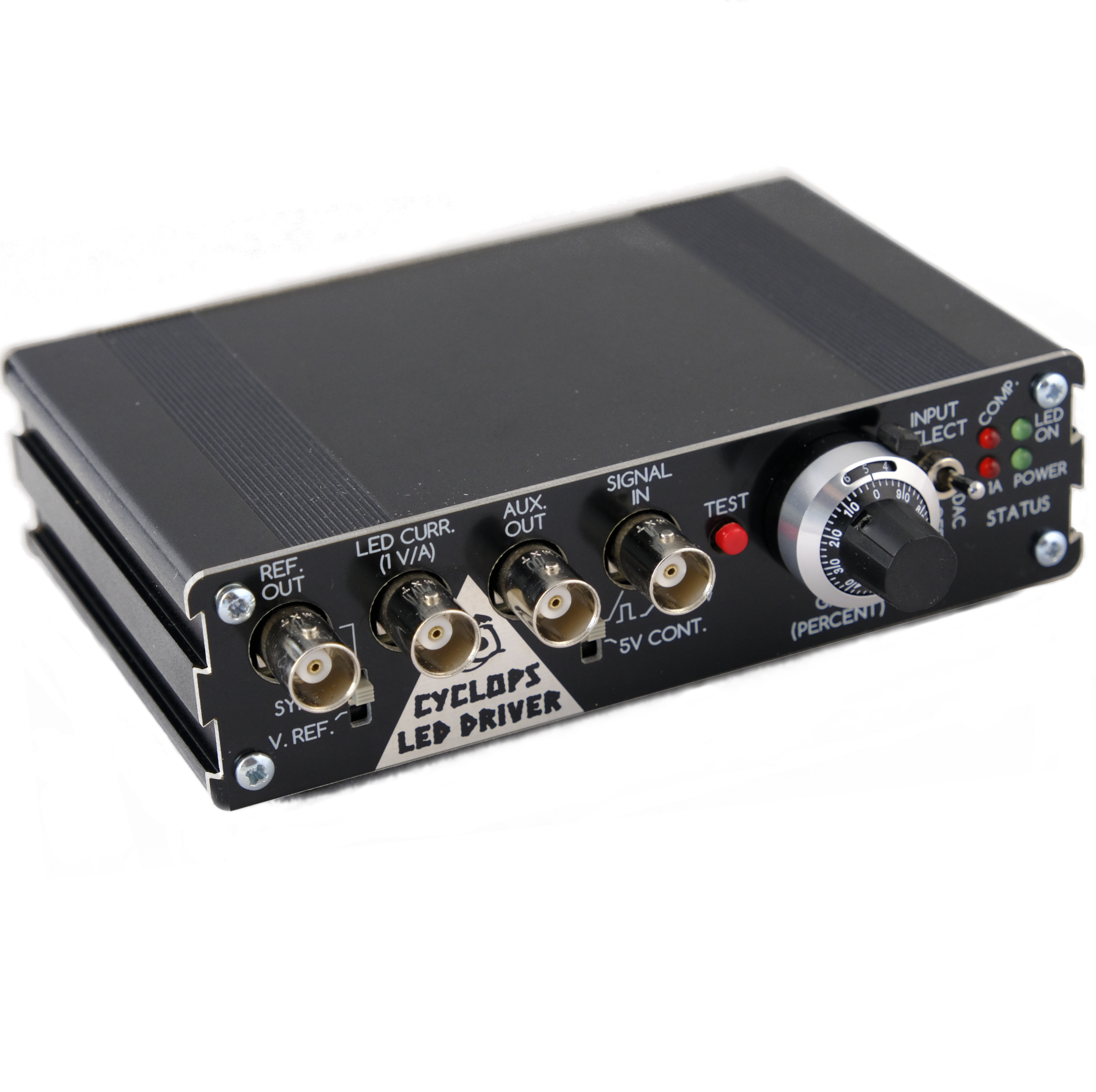
Cyclops LED Driver
Ultra-precise control of light power for optical stimulation
Description
Cyclops is an open-source LED driver that enables extremely precise control of light power for optogenetic stimulation. The circuit was developed by Jon Newman while in Steve Potter's lab at Georgia Tech in order to complete his thesis work, which required the delivery of ultra-precise, continuously time-varying light waveforms for optogenetic stimulation [1]. This was, and still is, not possible with commercial hardware for optogenetic stimulation. Since its first use, the circuit has been continuously improved in terms of speed, precision, programmability, and ease of use.
Features
Circuit Features
- Ultra-precise
- High power
- Up to 1.5A per LED
- Wide bandwidth
- > 2MHz optical modulation
- < 100 ns 1.0A rise and fall times
- Current and optical feedback modes
- Built-in waveform generation
- Programmable over-current protection
- Modular
- Arduino compatible
- Up to 4 synchronizable optical channels
- Accepts external analog, gate, or trigger inputs
Stimulus Generation Options
- External stimulus sequencer
- e.g. pulse pal or master-8
- External digital trigger
- e.g. TTL level from Arduino
- External analog waveform generator
- 0-5V analog signals
- Internal 12-bit DAC driven by Teensy
- Synchronized across up to 4 drivers
- Powerful Arduino library
- Programmable triggering logic
- Respond to USB input
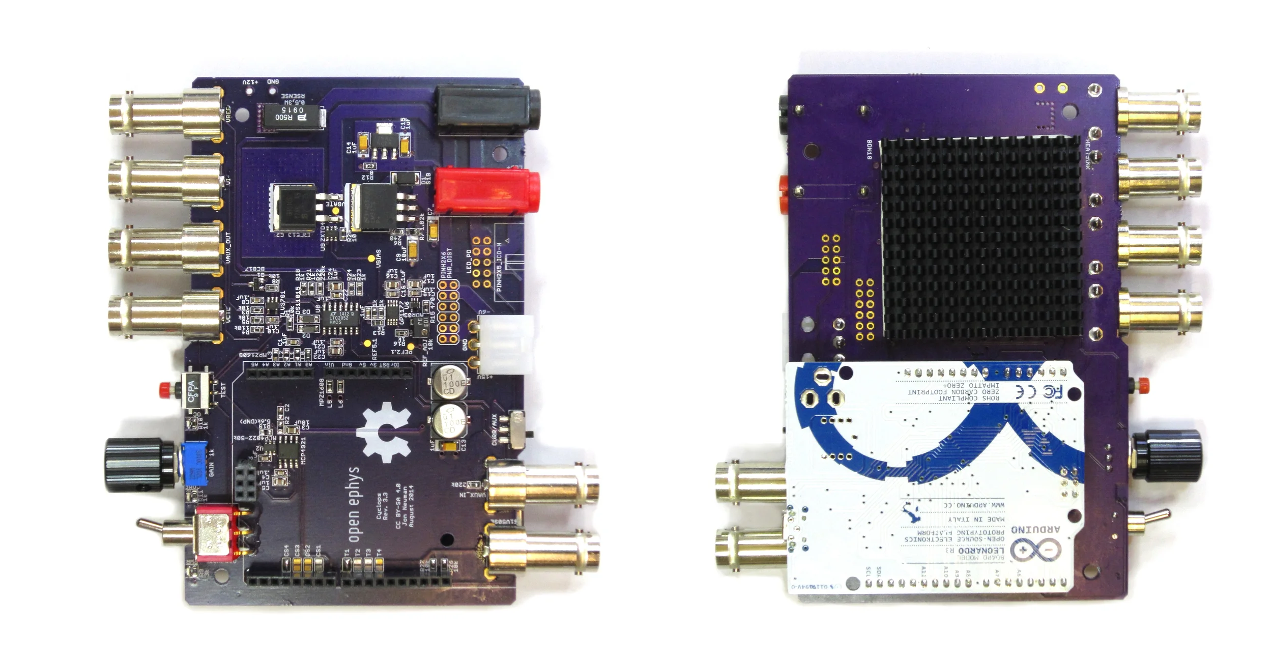
Cyclops Revison 3.3
Head-to-head
The table below provides a comparisons between Cyclops Rev. 3C and various commercially available LED drivers. Measurements were performed using the same signal generator and LED across drivers. Optical characteristics and optical feedback signal for the Cyclops driver were provided by a Thorlabs PDA36 amplified photodiode set to 0 dB of transimpedance gain.
| Plexon LD-1 | Plexon PlexBright1 | Thorlabs DC4100 | Cyclops (Current FB) | Cyclops (Optical FB) | |
| Speed | |||||
| 10-90% rise time2 (μs) | 49 | 76 | ? | < 0.1 | 0.53 |
| 90-10% fall time2 (μs) | 39 | 89 | ? | < 0.1 | 0.46 |
| Dead time, worst case2 (μs) | 140 | 160 | ? | 1.0 | 1.0 |
| Small signal -3dB bandwidth4 (kHz) | 10.5 | ? | 1003,5 | > 2500 | > 2500 |
| Accuracy | |||||
| Overshoot2 (%) | 0 | 0 | ? | 1 (Depends on LED cabling) | 1 (Depends on LED and photodetector cabling) |
| THD6 (%) | 8.29 | ? | ? | 8.2 | 0.41 |
| Power | |||||
| Max current drive (mA) | 1200 | 1100 | 1000 | 1500 | |
| Features | |||||
| Independent LED channels | 1 | 4 | 4 | 1 (modular; can stack up to 4 devices) | |
| Regulated current output | ✓ | ✓ | ✓ | ✓ | N/A |
| Regulated optical output | ✗ | ✗ | ✗ | N/A | ✓ |
| Programmable, hardware-based overcurrent protection | ✗ | ✗ | ✓ | ✓ | |
| Internal arbitrary waveform generation | ✗ | ✓ | ✗ | ✓ | |
| Independent DAC for each LED | N/A | ✗ | N/A | ✓ | |
| Modular design | ✗ | ✗ | ✗ | ✓ | |
| Manual pulse | ✓ | ✗ | ✗ | ✓ | |
| Outputs | None | None | None | Reference voltage, LED current, optical power (if measured) | |
| LCD display | ✓ | ✗ | ✓ | ✗ | |
| Programmability | |||||
| Open-source | ✗ | ✗ | ✗ | ✓ | |
| Driver | N/A | "Radiant" software | NI-VISA based GUI and API | Arduino compabile | |
| Interface | N/A | GUI/USB cable | GUI or API/USB cable | Arduino IDE/USB cable | |
| Waveform generation performance | N/A | 10 kHz aggregate update across channels | N/A | 100 kHz/channel update; evolves with Arduino tools | |
| OS compatibility | N/A | Windows | Windows | Windows, Linux, Mac | |
| Cost | $700.00 | $5300.00 | $3059.07 | ~$160.008 | ~$200.008,9 |
- Essential drive circuit consists of an Opal-Kelly XEM6001 FPGA Dev board tied to 4 commercially available buck converters from Recon.
- Test signal: 500 Hz, fully off to on 50% duty-cycle square wave resulting in 1A peak to peak through LED.
- Test signal: 1 kHz 500 mA offset, 100 mA peak-to-peak sine wave.
- Not measured on the bench top. Taken from manufacturer's specifications.
- Bandwidth threshold (e.g. -3 dB) was not specified. Applies to sine wave only.
- Test signal: 1 kHz 500 mA offset, 1A peak-to-peak sine wave.
- Includes the cost of the DC4100-HUB which is required to drive four LEDs.
- Approximate materials cost.
- Increased cost compared to current feedback mode is due to amplified photodiode (design included with Cyclops repository).
Theory of operation
High power light-emitting diodes provide adequate optical power for effective neural excitation and inhibition using modern optogenetic tools. LEDs are generally well behaved in comparison to the cheap diode-pumped solid state lasers that are typically used for optical stimulation. Even so, although many papers imply that the usage of LEDs is as simple as turning them 'on' and 'off', care must be taken to ensure stimulus stability, fast and fall times to take advantage of fast optogenetic channels and pumps, proper thermal and over-current management, and linearity when delivering complex stimulus waveform. The Cyclops driver simplifies these tasks while providing greatly improved performance over commercial alternatives in terms of bandwidth, linearity, modularity, and customizability.
Drive circuitry
The main functional component of the device is a feedback assisted, power, enhancement-mode N-MOSFET. Current is drawn from the source pin of the FET in accordance with one of two feedback modes: current feedback or auxiliary feedback. In both modes, the FET acts as a precision resistor whose resistance is changed in inverse relation to the gate voltage. The difference between the two modes is in how the gate voltage is regulated.
In current feedback mode, the gate voltage is adjusted such that the voltage drop across the sense resistor is equal to a DAC supplied reference voltage.
In auxiliary feedback mode, an external voltage that has a positive and monotonic relationship with optical power is provided as a feedback signal. This is typical provided by an amplified photodiode to linearize the relationship between a DAC supplied reference voltage and optical power.
Current feedback Using the circuit in current feedback mode ensures that the forward diode current across the LED is precisely modulated according the the voltage at the VREF pin. This configuration is a standard method for driving LEDs because the relationship between current and LED irradiance is smooth and monontonic. This means that more current across the LED will generate more light power (while staying within the LED's maximum ratings, of course). However, the relationship between current and irradiance is not linear - for most LEDs, it looks more like a logarithmic function. Additionally, the efficiency of the LED is inversely related to its temperature. So, as the LED operates and heats up, the amount of light it produces drops even when the current is held constant. The severity of an LED's temperature dependence and current/irradiance nonlinearity depend on the type of LED (the color and who made it). These properties should be clearly documented in the LED's data sheet. With a quality LED and proper thermal management, the effects of temperature and static current/irrandiance nonlinearity are fairly minimal and can be ignored.

Current feedback signal is proportional to current through LED.
Optical feedback. When extremely stable, linear control of light power is required, the auxiliary feedback port can be used to used to compensate for the temperature dependence and static nonlinearity of the current/irradiance relationship of the LED. For example, when the auxiliary voltage is supplied by a amplified photodiode that is somewhere indecent to radiation from the LED, the gate voltage is adjusted such that the measured light power matches a DAC-supplied reference voltage. This is the case in the circuit diagram. This configuration is referred to as optical feedback mode. A PDA36 adjustable transimpedance amplified photodiode from ThorLabs functions well for this purpose. However, you can make your own amplified photodiode for a fraction of the price (a design is included in the Cyclops repository). Optical feedback completely linearizes the relationship between a supplied reference voltage and the light power produced by the LED by compensating for its current/irradiance nonlinearities and temperature dependence.
Cyclops Licensing
Copyright Jonathan P. Newman 2017. This documentation describes Open Hardware and is licensed under the CERN OHL v. 1.2. You may redistribute and modify this documentation under the terms of the CERN OHL v.1.2. (https://www.ohwr.org/documents/294). This documentation is distributed WITHOUT ANY EXPRESS OR IMPLIED WARRANTY, INCLUDING OF MERCHANTABILITY, SATISFACTORY QUALITY AND FITNESS FOR A PARTICULAR PURPOSE. Please see the CERN OHL v.1.2 for applicable